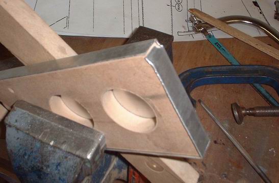
Making sheet metal parts with minimal tools† This is by no means meant to be the definitive guide to sheet metalwork, it is just a low cost option I use to make parts for the Spitfire project I am currently working on. Only the most basic tools are required, i.e. hacksaw, an assortment of clamps, hand files, a rubber faced mallet and some MDF or plywood with which to make the templates. † The method shown below describes the forming of a bracket required for the flight control framework on the spitfire. But the principle is exactly the same as used to make all the fuselage frames for the project. † †To start with you will need a template on which to form the bracket, as I am using 19 G bending quality sheet aluminium, MDF or plywood is strong enough for most of the templates, although this will depend on the number of parts being made on the template. Before making the template a few questions need to be answered regarding the finished size of the part. If the part has lips formed on one or all of the edges then this has to be taken into account when cutting the template, or the finished part will be one or two times the material thickness oversized depending on the number of lips. With this information known, the template can be cut to size less the material thickness for each lip on the finished part. The photo shows the template for the required bracket, the template is also pre drilled for rivet positions (small holes), three bolt holes and the large holes for the forming of the swages on the bracket. †
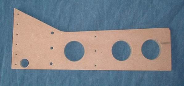
Next job is to cut the aluminium blank for the part required, this also has include the extra material required to form the lip or lips. On the bracket made below this required the blank to be cut 1Ē over size, the blank profile also follows the shape of the finished part when cut as can be seen in the photo.
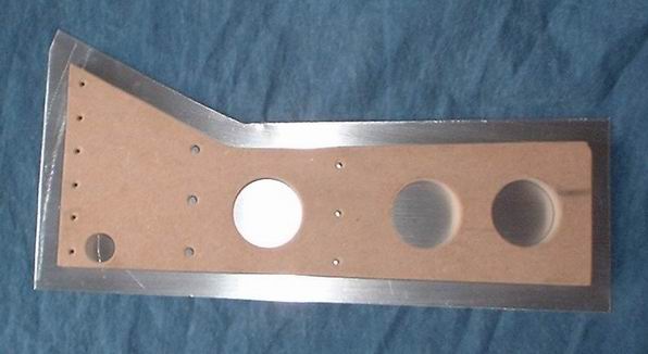 † †
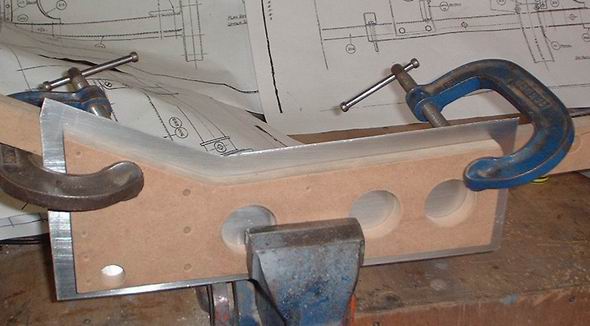
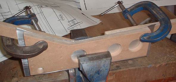
So with the template clamped in position the forming of the lip can begin. As the bracket has quite tight radii, I started working the sheet at the centre of the radius working outward from this point. †
 † †
†
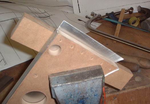
With the first lip formed, the bracket is turned over and the base lip is formed next.
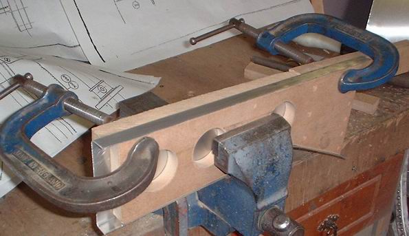
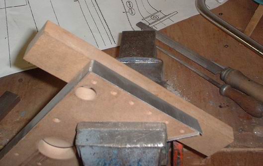
†† Next job is to form the lips on each end of the bracket.
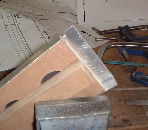
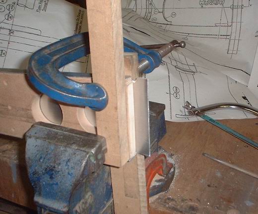
† The same process repeated for the opposite end.
† 
† Photo showing the formed profile of the bracket.
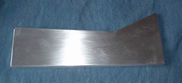
† Next job is to mark out the holes for the swage positions. These can then be chain drilled and filed out as shown below.
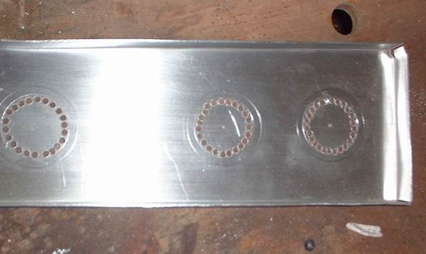
†The finished holes ready for swaging.
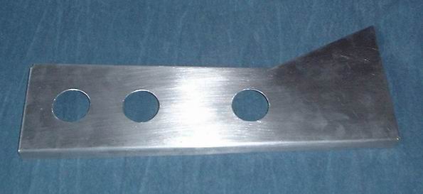 † †
The following photos show the method used to swage the holes in the bracket. Itís also worth remembering if the swages are on the same side as the lips, or facing the opposite direction.
So, with the bracket clamped to the template the first hole is ready for swaging. The punch to form the swage is made from hardwood, as I would be using this many times on other parts for the project.
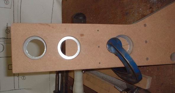 † †
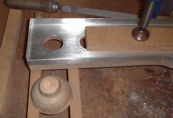
With the punch located in the hole, all thatís required is a couple of smart blows with the mallet to form the swage.
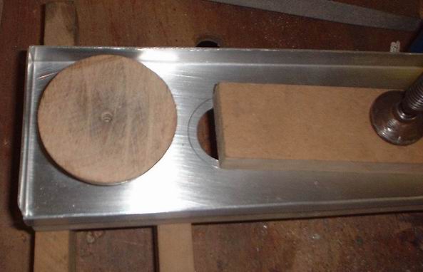 † †
The next photo shows all the holes swaged.
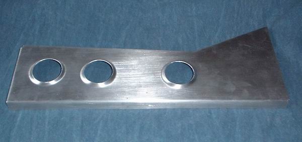 † †
The last job to done on the bracket is to drill the rivet hole positions and the other holes required on the finished bracket. The former is place back inside the bracket and then used as a drill jig, this method ensures that the rivet holes will line up when the bracket is assembled to the fuselage frame.
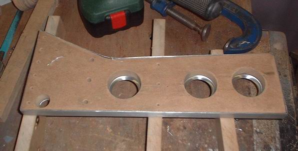 † †
The last photo shows the completed bracket.
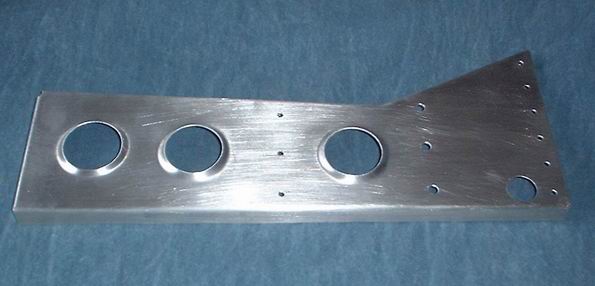
†
† I hope the method shown above gives some ideas on the making of sheet metal parts for your project, and hope some of you found it helpful. † Thanks for taking time to look † Dave
|
